I recently had a tapestry frame that I had produced for a customer a few years ago back in the framing workshop for the replacement of the existing front mount board with an new lighter cream coloured one. The process allowed me to re-examine and photograph my previous work for inclusion and discussion in this article.
Needlework or stitched artwork is created on a variety of substrate materials, ranging from thick holed loose weaved canvas, to narrow weaved canvas, to cotton or finer more densely packed textiles. There are also some needleworks that have no substrate like laces, and these require different mounting techniques to other stitched works.
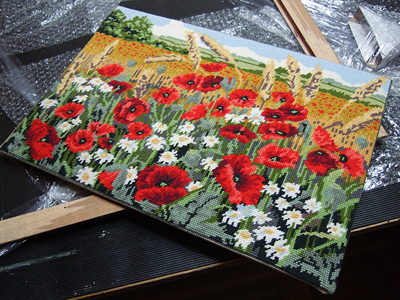
A stretched tapestry on foam board backing
Mounting needlework
To mount and frame most needlework created on a textile or meshed canvas substrate (like tapestries or cross-stitching), stretching of the fabric is required over a rigid material in order to flatten it’s surface (remove wrinkles, and distortions) and make it more presentable as a piece of artwork.
Some framing businesses can refuse to do needlework mounting and framing because of the extra time involved in the process of stretching. A needlework framing job can take an hour or more of extra time (plus extra materials) to complete compared to a regular paper based artwork framing job. As a result, the framer has to take this into account in the frame price, which in turn can lead to quite expensive framing jobs for the owner!
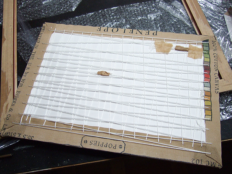
Laced tapestry stretched over foam board
Stretching the needlework
One method of stretching the needlework is to stretch it over a 5mm thick piece of white conservation foam board. The white foam board face will ensure that the stitch work looks bright and clear (especially if it is a slightly transparent white material). The 5mm thickness of the foam board is enough to provide suitable rigidity for the stretching process.
The needlework has to be pinned down into position, and then laced similarly to shoe laces but in both horizontal and vertical directions. The ends are tied away and it should resemble a criss-cross laced pattern on the back as shown in the image on the right. The choice of lacing should be suitable for the material being stretched. In this case a thicker cord has been used as there are wide holes in the tapestries open weave canvas substrate.
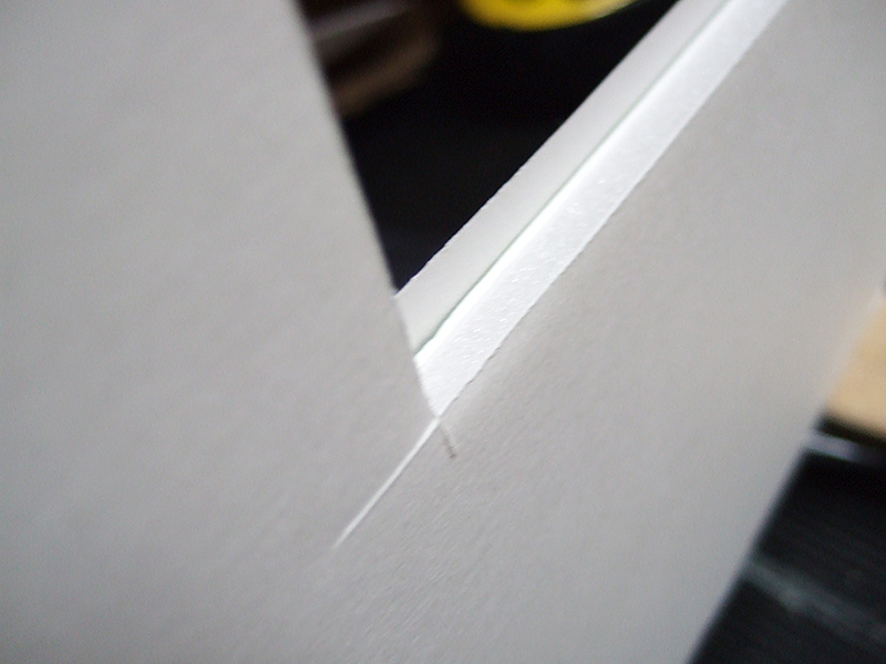
Foam board recess on rear of mount
The mount
The mount used for surrounding a needlework, should have a foam board surround on its back side, shaped to fit the stretched and laced needlework. The mount bevel edge is sized to overlap the foam board so it is not seen. It also should hide the rougher edges of the stretched tapestry artwork. The mount itself is a triple mount which keeps the raised texture of the tapestry off of the glass surface.
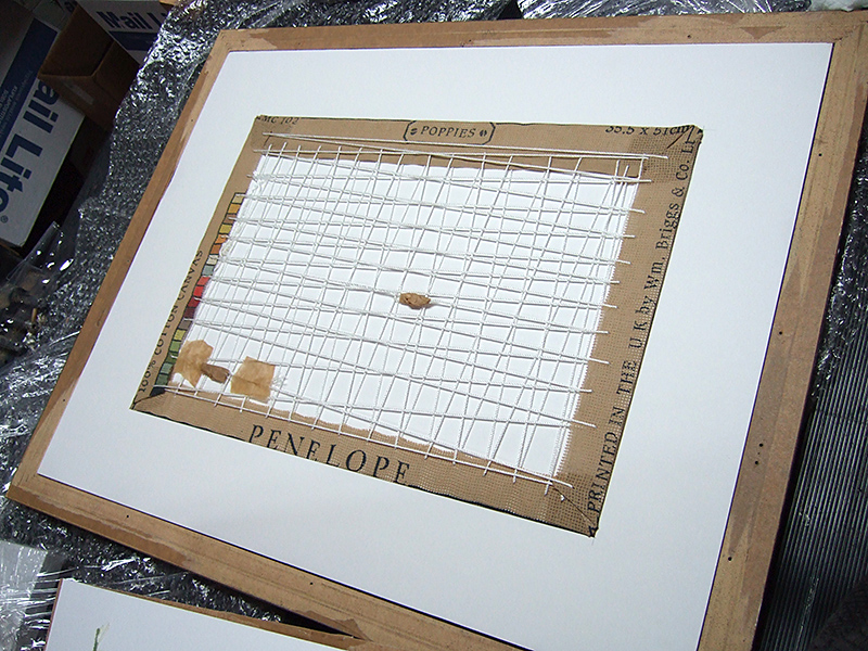
Stretched tapestry sitting into foam board mount recess
Finishing the frame
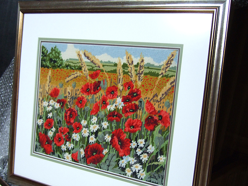
Once the needlework has been stretched, it can then be placed into the mount and will look like the image on the right. There should be no slack between the stretched needlework and the surrounding foam board. This will prevent the stretched needlework from moving within the mount. It’s now time to replace the backing board and finish the frame off.
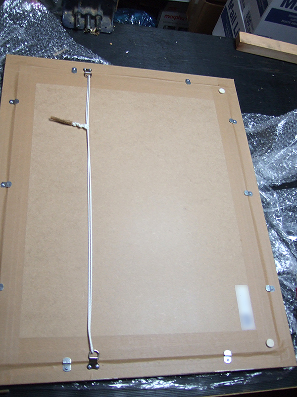
Reassembled frame with backing board attached
The frame back is completed with backing tape, several canvas offset clamps (as the thick mount is deeper than the frame rebate), D-Rings, felt pads and low stretch picture cord.
The finished frame front is shown in the first picture in this article.
A multi-aperture picture mount is a mount that has multiple openings to accommodate more than one picture in the same mount (and ultimately in the same picture frame). It can be used to group similarly themed photographs or pieces of artwork together. Openings can also be made (if desired) to place titles into the mount which can describe the content.
A multi-aperture mount can be created using even the most basic of mount cutter systems.
The majority of work involved in making a multi-aperture mount should be focused on the planning stage. A well planned approach, including an accurately calculated mount size, choice of board colour, and a detailed sketched outline is required to eliminate potential errors (and wasted board) before any cutting is ever done.
Good planning of the multi-aperture mount is critical to success.
In the following example of a multi-aperture mount I have 3 similarly sized small photographs of a dog. More complex variations of photos, eg all differently sized, would require an even more careful planning and measuring.
In this particular case, there is a straightforward choice of either horizontal or vertical placement of the photos with no title. The customer had chosen vertical placement so I planned around this. Sometimes, although not always, the order of the photos or artworks will be important so it is always best to check with the customer. You can lay the photos on to a piece of mount board to help you with your choice of layout as well as choice of mount board colour. In this case I am just using a whitish cream colour, but quite often more colourful boards work well too. You will just need to experiment!
The sketch of your plan is important to list all the spacings and sizes as well as providing a visualisation of your project.
After you have created your layout and chosen the colour of mount board, the next step is to plan it with a sketch. I usually just do a rough and ready drawing on a scrap piece of paper or mount board. In this case, I have measured the photos (cropped) to be 95 x 95 mm each and I want to lay them out with a 30 mm internal gap between each one. The spacing to the outside of the mount should be double this value to look correct. I have also added in 5 mm extra per side making it 65 mm spacing to allow for the 5 mm of rebate of the frame. This will mean that the visible mount (after being framed) will be 60 mm around each outside edge.
I then add up the totals in each dimension (65+95+30+95+30+95+65) = 475 mm in height and (65+95+65) = 225 mm in width. This will be my outside edge mount size. I will then cut both my mount and backing boards down to this size.
Measuring spacings for one of the apertures. Measurements should be referenced to the outside board edge not cumulatively to each other.
Once I have the front mount board I can start to measure and draw the pencil plan on the back side of the board (always use pencils, you can erase the lines to make changes, and they don’t leak ink!).
Note: when you sketch on the back of the board, be aware that it will be the mirror image of what will appear on the front. In my example, it won’t be any different, but if you have different sized images it is something that needs to be taken into account).
The fully planned and measured mount back with apertures shaded and ready to cut them out.
Measurement and drawing of a 65 mm edge is done by starting from the outside of each edge of the mount board. Measurements should be referenced to the outside board edge not to each drawn line as errors can have a cumulative effect. We measure inwards to include the pencil outline for each mount aperture. Once you have completed this exercise you should have something that shows where all the aperture cut-outs will be. I usually shade these areas in to highlight them as there can be so many lines sketched out that you can easily get confused when doing the actual bevelled cuts into the mount board with the mount cutter.
It’s time to start cutting the mounts – you can use any mount cutter to do this, but some of the more sophisticated systems can actually be harder to use with multi aperture mounts as you will have to rotate the mount 360 degrees when cutting out each aperture. This can be an issue with bigger or longer multi-aperture mounts which can be obstructed by some of the larger mount cutters’ arms and stops. For this reason, I generally use a hand held mount cutter system which gives me the room and flexibility that I need to move the mount around unrestrictedly whilst cutting it. In this case I am using a short Logan Adapt-a-rule with a pull cutter head. Remember while mount cutting that, as with every other mount cut, you have to use a slip mat behind the mount to cut into at all times. This is easy to forget as you move the multi aperture mount around, but failing to do so will result in bad cuts and bevels.
Starting to cut out the mount apertures one by one.
I then start to cut each aperture out. It is important to always focus on one aperture at a time. After cutting one opening out, I make a point of using masking tape to stick each cut out aperture back in temporarily to the mount to preserve each mount bevel as I continue to work on the other apertures. This approach also provides a flat surface for the mount cutter to operate on.
The finished mount minus the photos.
When cutting a multi-aperture mount, it is easy to get distracted and cut the wrong line or edge. To avoid this I use the following rule – make sure each of my shaded aperture patches is always visible to the right of the mount cutter head before doing a cut. If you don’t follow this approach, you could end up cutting a few reverse bevels, which would mean a complete restart.
After cutting the 3 apertures out, the mount now looks like the picture on the left (with backing board behind it in this case). The backing board should be attached to the front mount along its longest edge (for stability purposes) with ph7-70 acid free conservation mounting tape. Creating a hinged mount.
Fitting the photos to mount with T hinges
Its now time to add in the photographs. Each photograph can be stuck down with two T-hinges per photo. Alignment/positioning of the photo with the mount can be checked before permanently holding them in place with the T- hinges.
Once this is completed, the multi-aperture mount is now finished and is ready to be framed.
Examples of multi-aperture mounts –
A wedding themed multi aperture mount
1. A wedding multi-aperture mount with title added and framed. A simple layout, but balanced geometrically with a centrally placed title opening. It is also important to make the title look good using a nice font and printed on high quality, textured paper rather than cheap bright white printer paper.
A wartime memorabilia themed multi-aperture mount
2. A complex 3D multi-aperture mount to display wartime memorabilia. In this case I had the challenge of creating 3 apertures, one to accommodate a pencil sketch, but two more for the 3D objects (wartime medals and a military service book).
 I recently had a tapestry frame that I had produced for a customer a few years ago back in the framing workshop for the replacement of the existing front mount board with an new lighter cream coloured one. The process allowed me to re-examine and photograph my previous work for inclusion and discussion in this article.